

SITCOMTN-152
Collimated Beam Projector Installation and ComCam Testing#
Abstract
Report on the initial installation and testing of the laser and Collimated Beam Projector during the ComCam campaign. We include an in-depth discussion of the measurement of the ComCam g and r band filter throughputs.
Introduction#
The Collimated Beam Projector (CBP) is a calibration tool to enable very precise measurements of the throughput of the Rubin optical system. With a monochromatic collimated beam directed at the primary mirror, we are able to both avoid scattered light and know precisely the amount of light that we are sending into the telescope. The beam is much smaller than the primary mirror, and does not fill the pupil, but by moving the CBP relative to the telescope, we can over multiple iterations illuminate all parts of the mirrors and focal plane. The CBP represents a novel approach to calibration for precision photometry. For that reason, it was critical for us to gain some experience with it before LSSTCam. We were able to get a few nights of testing right before ComCam was removed. The data collected is invaluable, and the experience gained and the results will enable us to be prepared for the LSSTCam On-Sky campaign.
The primary use of the CBP will be to measure the wavelength-dependent throughput of the Rubin telescope and LSSTCam with high precision. Additionally, it will allow us to do the following:
Look for reflectance and transmission variations across the mirrors and filters.
Study ghosting of the Rubin filters and LSSTCam.
Measure cross-talk nonlinearity.
Look at pointing offsets created on parts of the mirrors when AOS applies bending mode corrections.
CBP Design#
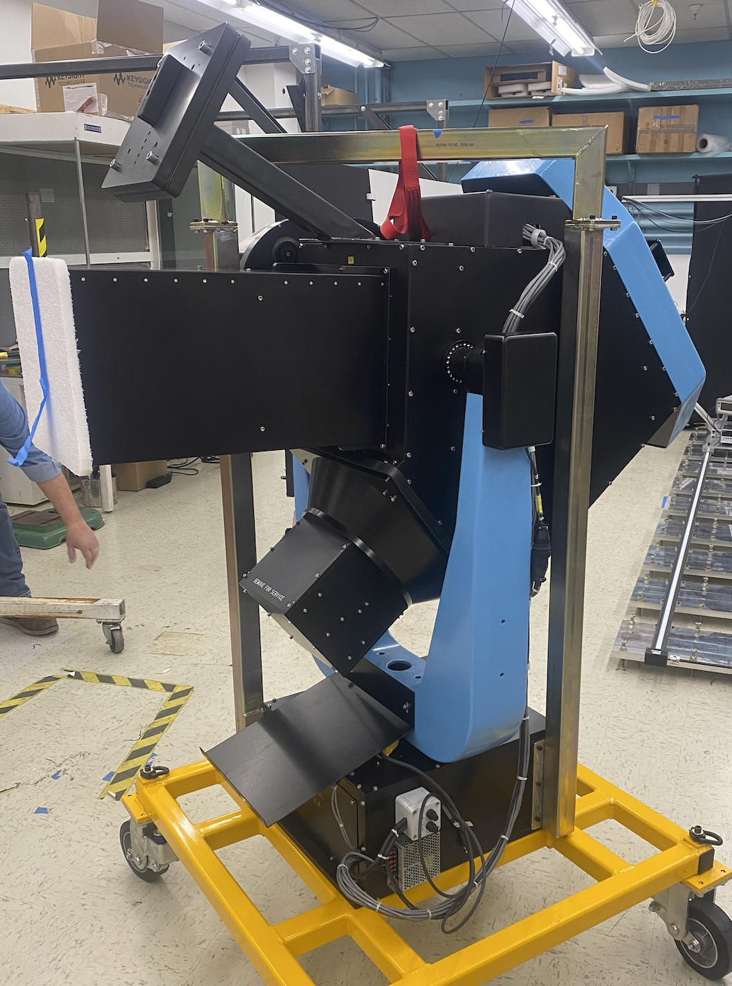
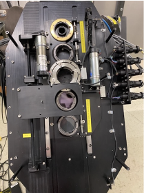
The CBP, a Schmidt reflector run in reverse, has a focal length of 625 mm and an aperture of 240 mm. It has slots for five different masks. We use an Ekspla NT242 tunable laser fiber fed into a 6” integrating sphere to illumminate the focal plane. A NIST-calibrated photodiode in the integrating sphere is read out by an electrometer and can then be used to determine the amount of flux sent to the Simonyi Telescope (see SITCOMTN-106).
|
|
Figure 1: The CBP in the lab in Tuscon before shipment (left) and the CBP mask holder (right).
Mask Design#
The magnification factor of the CBP mask to the ComCam image is a ratio of the focal lengths, so approximately a factor of 16.
For ComCam, we left one slot empty, and we filled the remaining four slots with four different masks. One mask is a 1mm pinhole from Thorlabs, which we will use with a calibration system to calibrate the CBP to an external source, but did not use during the ComCam campaign. The other three masks are custom designed 1” photolithographic masks that we used for tests during ComCam. They are:
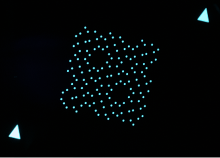
A single 100 um pinhole for every amplifier on ComCam, offset so that when properly aligned the crosstalk does not intersect with any other pinhole.
A single 150 um pinhole for every CCD on ComCam.
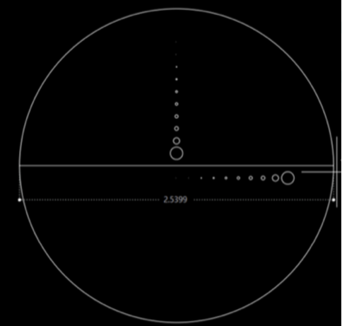
A test mask with two lines of pinholes with sizes 10 um, 20 um, 50 um, 100 um, 150 um, 200 um, 250 um, 300 um, 500 um, and 1 mm.
|
|
Figure 5: The one-pinhole-per-amp mask illuminated with a blue LED (left) and the design for the mask with two lines of pinholes of varying sizes (right).
CBP Repair#
During the shipment of the CBP from Tucson to Rubin Observatory, it suffered from considerable damage. When the crate was opened, it was found that the dew shield that held the Schmidt correct fell off and there were metal shavings and sawdust everywhere. The CBP was transferred down to La Serena where a more detailed evaluation took place. Damage was found on the mask changer stage drive arm, azimuth drive shaft, and both azimuth and elevation drive disks. This damage is consistent with one hard drop during shipping and with the CBP crate having spent many hours on a truck on gravel roads with poor suspension.
|
|
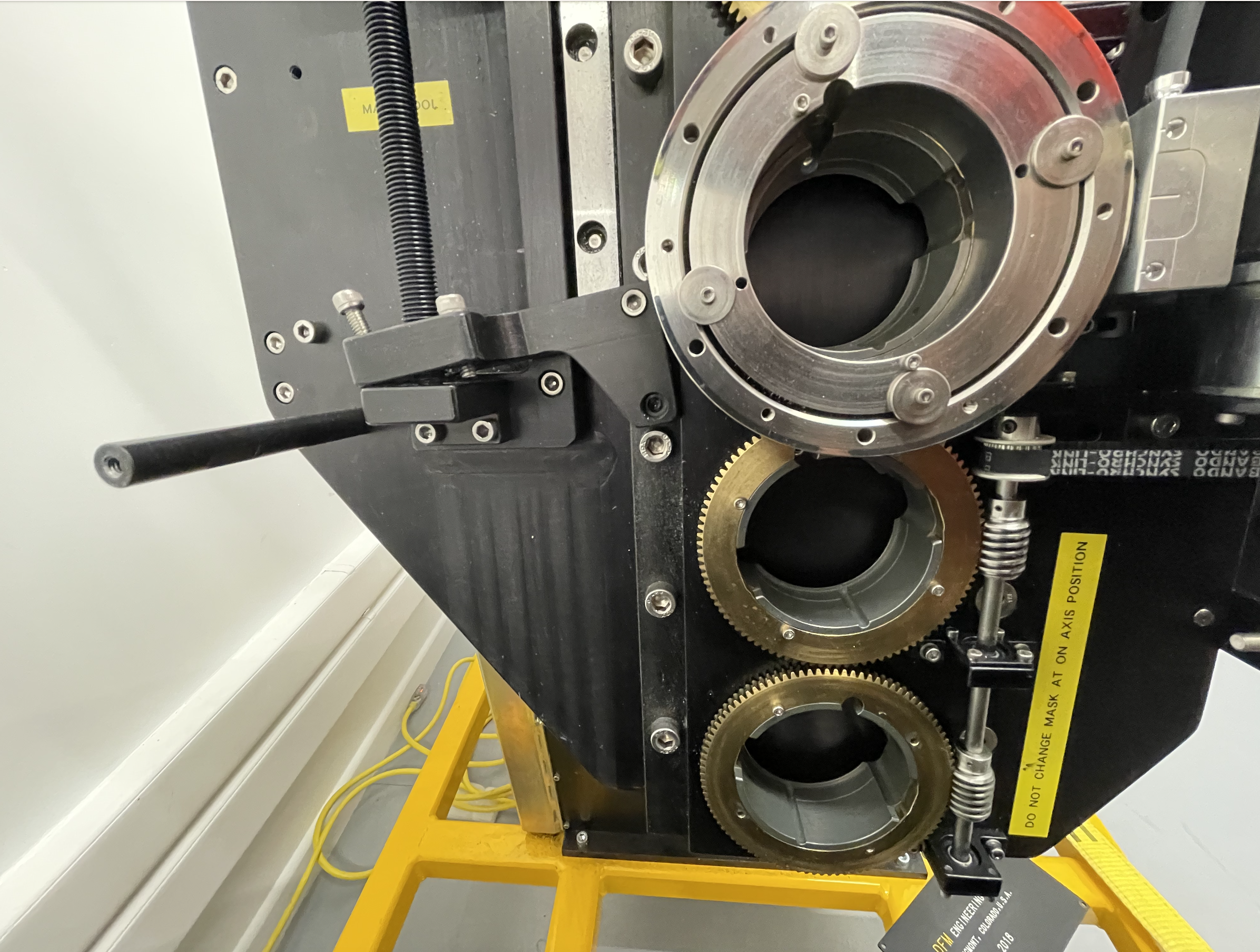
|
Figure 2: The CBP arrived on summit damaged. From left to right, the dew shield fell off, screws came out, and the mask changer stage arm broke.
Fortunately, although the planar mirror was superficially scratched, there was no major damage to the optics, and thus we were able to repair the CBP. We transported the CBP back down to La Serena, where we disassembled the CBP. The machine shops in La Serena and Tucson made replacements for the broken parts, and added many new holes for screws both to replace the stripped holes and to make the CBP more secure in case of future earthquakes. Following the repairs in La Serena, the collimation of the CBP was tested based on the vendor’s instructions. We found that the collimation was consistent with measurements in Tucson. While we were unable to complete more than basic functionality and collimation, we decided to transport the CBP back to Rubin Observatory.
After arriving at the Rubin Observatory summit and getting secured in the laser lab, we completed throughput tests of the CBP using the Ekspla Tunable Laser. The results were generally consistent with what had been measured in Tucson. Functional tests were performed and final preparations were made for installation on the dome.
|
figure:: images/CBP_dome_front.png :width: 400px
Figure 3: The repaired CBP. Notice that there are many more screws visible around the dew shield.
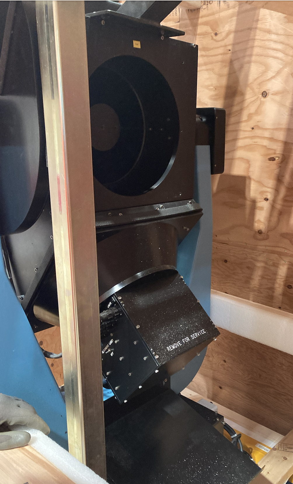
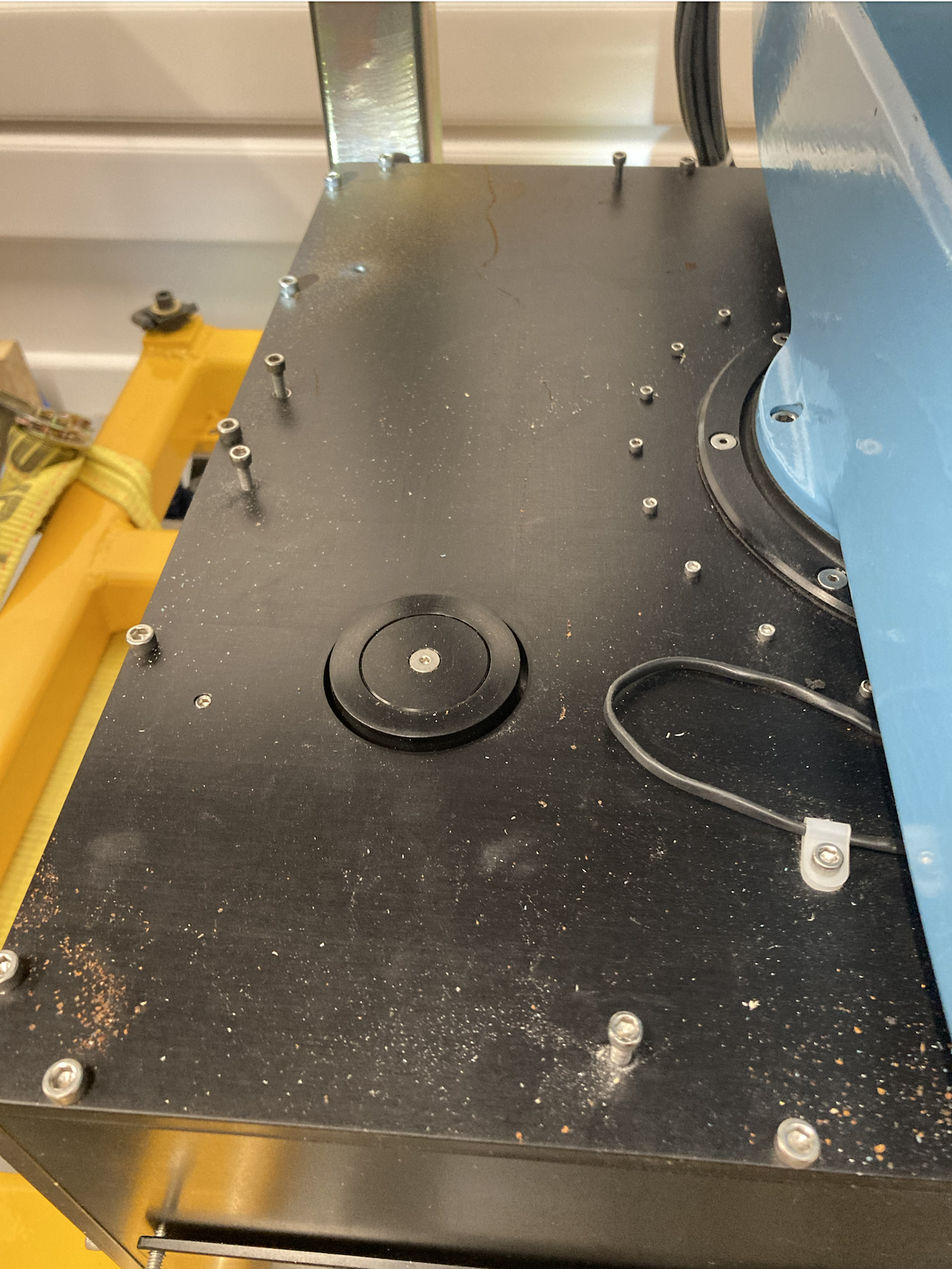
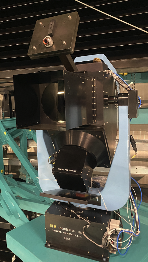
CBP and Laser Installation on Dome#
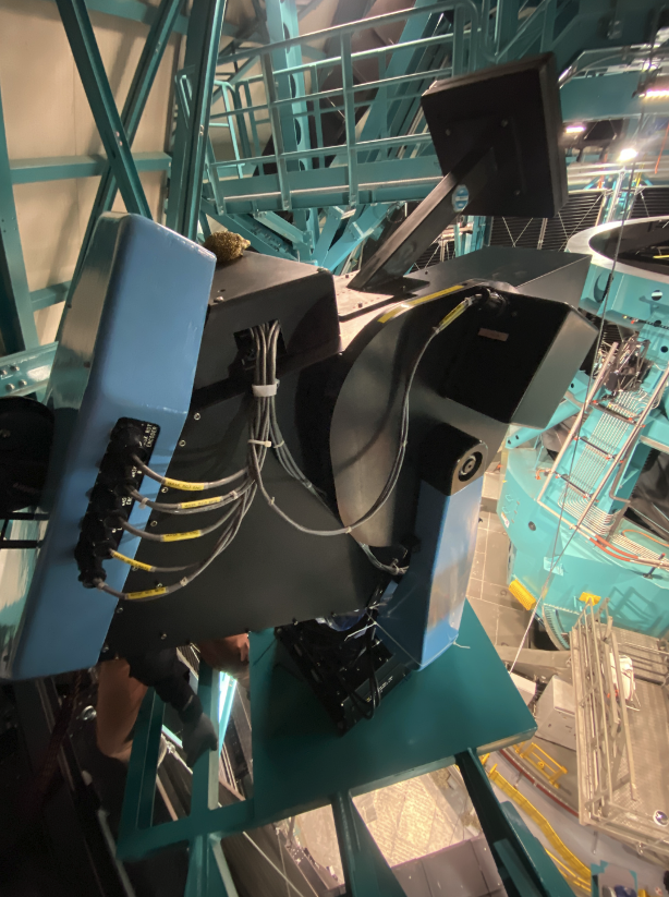
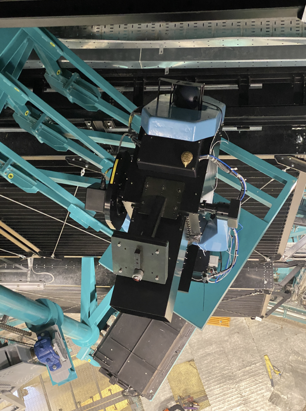
The CBP, with a custom lifting fixture designed by the vendor, was lifted by the main dome overhead crane from L5 to L7. From there, rigging was attached to supports on the ceiling of the dome. Using the Tirak hoist, the CBP was lifted up to the upper platform beside the calibration screen structure. It was then pulled into place and secured to the platform with 4 bolts. Similarly, the laser enclosure was installed on the lower platform.
|
|
|
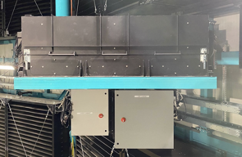
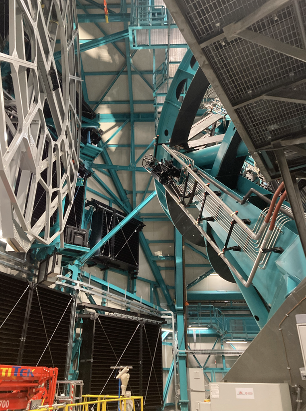
|
Figure 4: The CBP and laser installed on the dome. Top row shows the CBP in the dome from different angles. Bottom row shows the CBP and telescope pointing at each other (left) and the laser installed on the dome (right).
Thus, with heroic effort from the electronics, electrical, IT, and construction teams, we were able to install the CBP and laser, hook them up, and then take data with the CBP during the last four nights of the ComCam campaign.
CBP Testing with ComCam#
Here is a list of the major tests and milestones we were able to achieve:
We were able to copoint the CBP and the Simonyi Telescope.
We demonstrated that the copointing locations were repeatable from night to night even as the dome, TMA, and CBP had moved during the day.
We swept through focus for all of our masks.
We made small movements of the CBP and TMA to see how repeatable and accurate the movements were.
We performed a copointing ‘dance’ where we moved the CBP and telescope at the same time and kept the CBP spots on ComCam.
We swept through wavelengths in the g and r bands, to find our in-band, out-of-band, and band-edge throughput. We observed a red leak in the g band.
We took images to investigate nonlinearity in the crosstalk.
We took images while applying different AOS bending modes and saw how the spots moved.
We looked at diffraction off the channel stops from red light.
We measured a different CBP mask magnification on the ComCam focal plane relative to what we calculated, implying that the CBP focal length is slightly shorter than expected. We will take this into account as we design our LSSTCam masks.
|
|
Figure 6: The one-pinhole-per-amp imaged on ComCam (left) and the two lines of pinholes of varying sizes imaged on ComCam (right).
A more complete summary of the tests, along with the dates and sequence numbers of the tests can be found here. A detailed observing log from the four night campaign can be found at this link. For the rest of this report, we go into more detail on the filter throughput measurements.
ComCam Filter Throughput Measurement#
Data Taking Sequence#
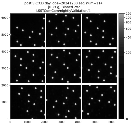
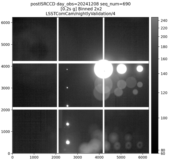
The CBP throughput measurement campaign on ComCam was performed on the 10th and the 11th of december 2024 on filters ‘g’ and ‘r’. The mask used for this study is the one per CCD with 150 um diameter CBP pinholes. The standard data sequence involves taking an image with the filter ‘g’, then with filter ‘r’, and finally without a filter (denoted by ‘none’ here). Then, a set of ‘dark’ images with the laser off are taken following the same order. Due to lack of time on the second day which was dedicated to scanning the filter edges, we switched to a second sequence. This sequence consists in taking an image with one filter immediately followed by an image with laser off for each wavelength, and then doing the same thing without a filter. For exposure time studies, there are some duplicate wavelengths. For both those sequences, half second electrometer readings were taken after every exposure. More details about the sequences and the analysis can be found on this confluence page.
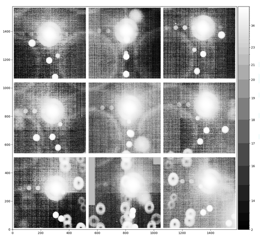
|
Figure 7: The one-pinhole-per-CCD mask with a scaling so that the ghosts are clearly visible. This mask was used to perform the filter throughput measurements.
Image Processing#
The images used in this analysis were reprocessed using a custom ISR configuration, which included only overscan subtraction.
Background Subtraction#
Background Images#
Some CBP exposures were taken during sunset, introducing additional flux contamination that varied over time. As a result, using the laser-off images as background estimators in such conditions introduced a time-dependent bias in the measured spot flux. The figure below shows the average count on the laser-off images versus the time of the day.
Since these images could not be used directly, an alternative method was implemented to ensure consistent background subtraction across all spots.
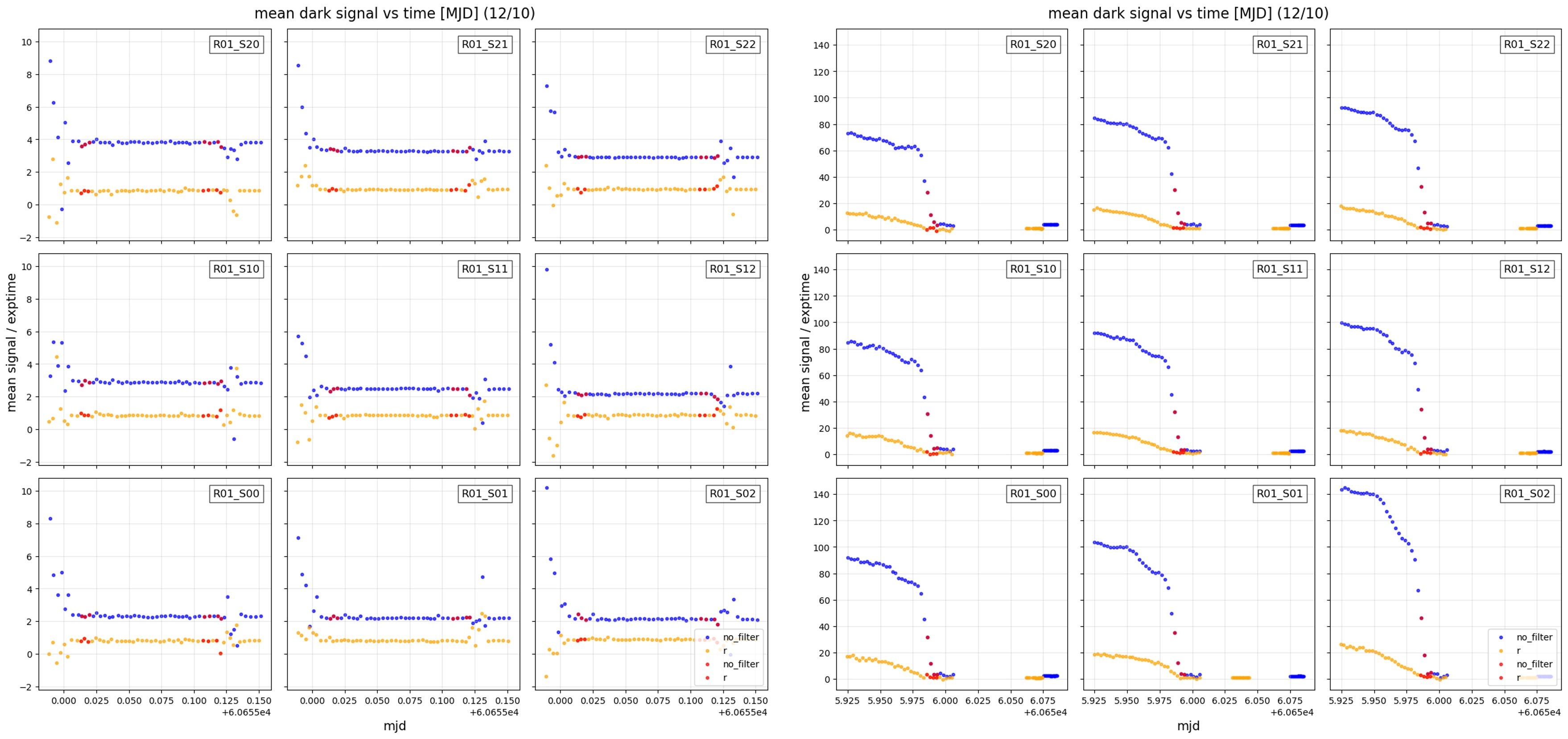
|
Figure 8: The mean background of the CBP images taken with the laser off over the course of the observations.
Renormalization with Photodiode Data#
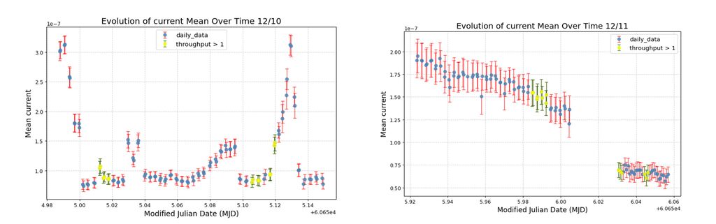
The photodiode measurements consist of recording electrometer data for 0.5 seconds after each exposure, providing an estimate of the laser flux. During the ComCam campaign, the photodiode operated in current mode, resulting in relatively large uncertainties (~10%) on the current measurements.
Normalizing spot fluxes using these data would therefore introduce an additional 10% uncertainty, which is undesirable given the precision required. As a result, we assume for this analysis that the laser flux is stable to within 10% at a given wavelength throughout the ComCam campaign.
|
Figure 9: The mean electrometer current for each measurement.
Workflow Schema#
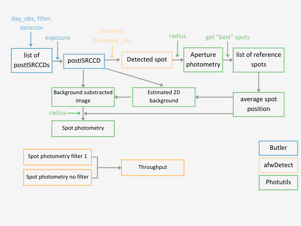
Thus, the developed workflow to compute the throughput does not include the laser-off images or the photodiode measurements.
|
Figure 10: The filter throughput workflow. Filter 1 denotes for either the g or r filter.
Spots Flux Measurement - Aperture Photometry#
Spot fluxes are measured using aperture photometry with a circular aperture of 200 pixels in radius, selected to encompass the largest spot size observed across all exposures. The aperture is centered at the mean spot position for each filter and each day of data taking as described above.
The radius choice was validated through a study of the dependence of the measured flux on aperture radius (see “Flux vs. Aperture Radius” figure). The photometry is performed using the photutils aperture photometry tools, applied to background-subtracted images using the background model described in the previous section.
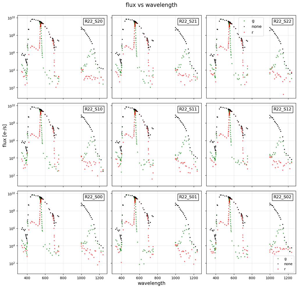
The figure below shows the measured spot flux as a function of laser wavelength for different filters, across the full ComCam raft.
|
Figure 11: The measured spot flux as a function of laser wavelength for different filters, across the full ComCam raft.
Filter Throughput Measurement#
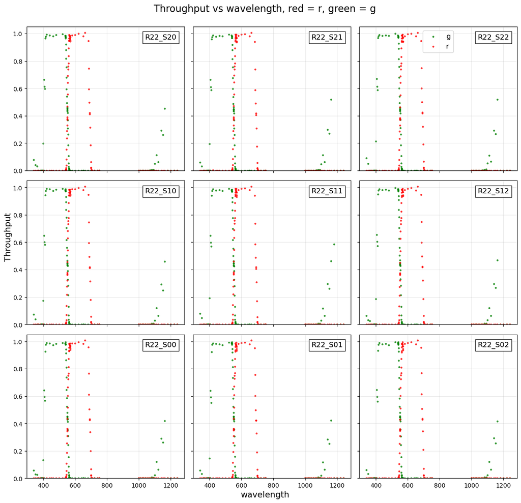
To compute the throughput of a given filter at a specific wavelength, we divide the measured flux of the spot with the filter in place by the flux measured with no filter.
By repeating this process across all available wavelengths (see table above) and for each CCD in the g and r filters, we obtain the throughput curves shown in the figure below.
|
Figure 12: The filter throughput measurements for the g and r filters. A red leak is very clearly visible in the g filter.
Summary and Next Steps#
Overall, the testing campaign with ComCam was very successful. We were able to demonstrate that the CBP works and to take the data that we need to design the masks we want for LSSTCam. In particular, we were able to measure the precise magnification factor of the CBP masks, image the ghosts, and measure the transmission of the g and r band filters. We saw evidence of red light leakage in the g-band, with the g band filter having around 50% transmission at 1190 nm.
We are currently completing the analysis of the data. We are also working on software to make the process of data collection more automated during LSSTCam.